Showing posts with label UML. Show all posts

Thursday, 5 May 2016

What are basic flowchart shapes ?


  • Terminator : Start / End
  • Process : Functions / Activities
  • Decision : Conditional statements
  • Data : Display / Read / Manipulate the data
  • Document : Save the data in documents
  • Connector : Go to next page


Sunday, 24 April 2016

How class relationships can be represented in UML ?


Classes in UML

Objects described by classes collaborate

Classes describe objects
  • Interface (member function signature)
  • Behaviour (member function implementation)
  • State bookkeeping (values of data members)
  • Creation and destruction
  • Class relations → object relations
  • Dependencies between classes


Relationships between classes
Structural relationship :
  • Association
  • Aggregation
  • Composition

Using relationship :
  • Dependency

Sharing relationship :
  • Inheritance

Friday, 22 April 2016

What are UML Building blocks - Things ?


UML Building blocks - Things

Structural Things
Structural things are the nouns of UML models.
These are the mostly static parts of a model, representing elements that are either conceptual or physical.
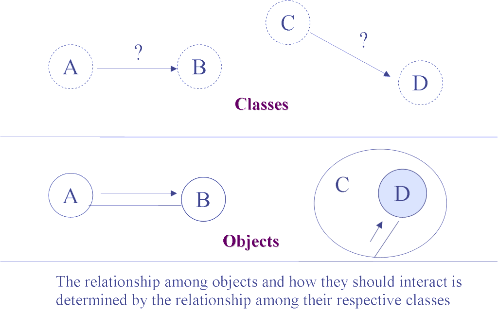
Class
A class is a description of a set of objects that share the same attributes, operations, relationships, and semantics.

  • Attribute : An attribute is a named property of a class that describes a range of values that instances of the property may hold.  
  • Operation : An operation is the implementation of a service that can be requested from any object of the class to affect behavior.


Use case
A use case specifies the behavior of a system or a part of a system and is a description of a set of sequences of actions, including variants, that a system performs to yield an observable result of value to an actor.

  • Actor : An actor represents a coherent set of roles that users of use cases play when interacting with these use cases.
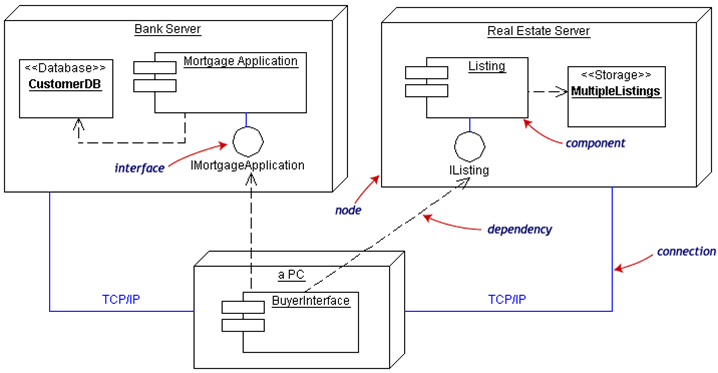

Interface
An interface is a collection of operations that specify a service of a class or component.

Collaboration
A collaboration defines an interaction and is a society of roles and other elements that work together to provide some cooperative behavior that's bigger than the sum of all the elements.

Active class
An active class is a class whose objects own one or more processes or threads and therefore can initiate control activity.
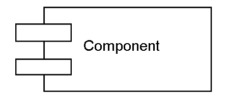
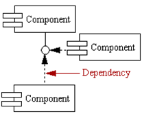
Component
A component is a physical and replaceable part of a system that conforms to and provides the realization of a set of interfaces.
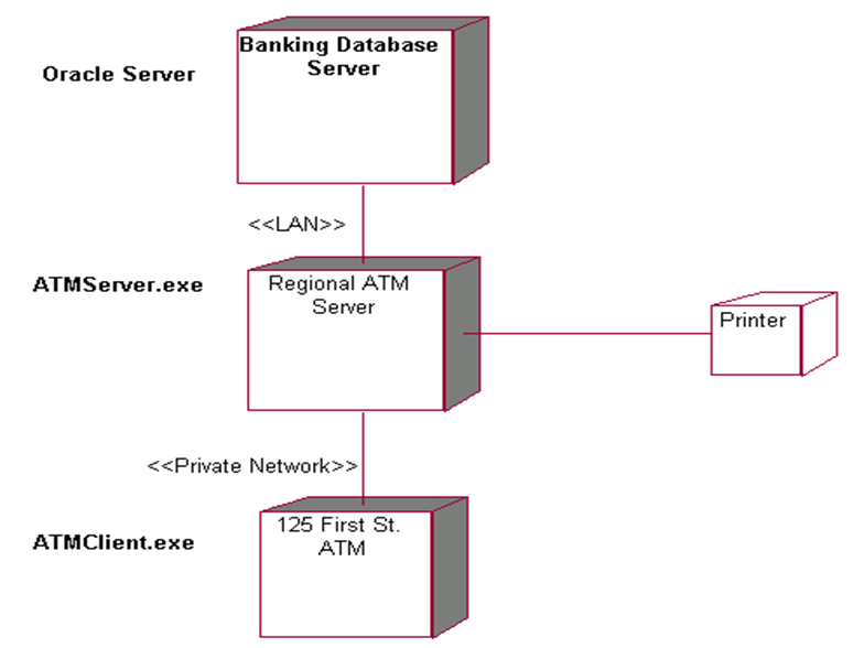
Node

A node is a physical element that exists at run time and represents a computational resource.


Behavioral Things
Behavioral things are the dynamic parts of UML models.
These are the verbs of a model, representing behavior over time and space.

Interaction
An interaction is a behavior that comprises a set of messages exchanged among a set of objects within a particular context to accomplish a specific purpose.

State machine

A state machine is a behavior that specifies the sequences of states an object or an interaction goes through during its lifetime in response to events, together with its response to those events.


Grouping and Annotational Things
Grouping things are the organizational parts of UML models.
Package
A package is a general purpose mechanism for organizing elements into groups.

Annotational things are the explanatory parts of UML models.

Note

A note is simply a symbol for rendering constraints and comments attached to an element or a collection of elements.

Thursday, 7 April 2016

How UML is related to OOAD ?

What are the modelling tools supporting UML ?


Modeling Tools Supporting UML
  • Rational Rose -  Rational Software Corporation
  • Enterprise Architect
  • System Architect  -  Popkin software
  • GDPro  -  Advanced software Technologies
  • Master Craft (AddEx) -  Tata consultancy Services
  • Object Analyst  -  Tata Technologies Limited
  • MS Visio

What is a Model and Modelling ?


In any software life-cycle, the suggested distribution of effort is : 
  • Requirements Capture : 15%
  • Analysis & Design :   25%
  • Implementation : 40%
  • Testing : 20%

Analysis - What is to be done ? ( What are the building blocks ? )
Design - How is it to be done ? ( How they should be put together ? )


Modeling

In object oriented approach,  Analysis phase  is accomplished by discovering classes and objects in the problem definition.

Design phase  is realized creating a software architecture , capturing  both the structure & behavior of the system.
Modeling is simplification of reality.

Modeling helps us achieve these aims : 
  • Models help us to understand the working of a system before actually building it.
  • Models permit us to specify the structure or behavior of a system.
  • Models give us a template that guides us in constructing a system.
  • Models document the decisions we have made.


Elements of a model


Notation: It is used as iconic language for expressing each model of a system.
                 These should be standardized notations.
Process: The activities leading to the orderly construction of the system models.
Tools:  It is the automated support to assist the process of analysis and design.

How to represent class relationships in UML ?


Classes in UML

Objects described by classes collaborate
Classes describe objects
  • Interface (member function signature)
  • Behavior (member function implementation)
  • State bookkeeping (values of data members)
  • Creation and destruction
  • Class relations → object relations
  • Dependencies between classes


Relationships between classes

Structural relationship :
  • Association
  • Aggregation
  • Composition

Using relationship :
  • Dependency

Sharing relationship :
  • Inheritance

What are the type of UML diagrams ?


UML Diagrams
  • Class diagramsrepresent the static structure in terms of classes and relationships.
  • Object diagramsrepresents object and their  relationships, it gives snapshot of the system at any given time.
  • Component diagramsrepresents the physical components of the application.
  • Deployment diagramsrepresents the deployment of components on particular pieces of hardware.
  • Use Case diagrams
    represents the functions of a system from the users point of view.
  • Sequence diagrams
    are temporal representation of objects and there interactions.
  • Collaboration diagramsare a spatial representation of objects, links  and interactions.
  • StateChart diagrams
    represents the behavior of a class in terms of its state changes.
  • Activity diagrams
    represents the behavior of an operation as a set of actions.

What is UML and its building blocks ?


What is UML ?
  • Modeling language
  • Graphical notation that OO methods use to express designs.
  • Language for visualizing, specifying, constructing and documenting the software artifacts.
    can be used to establish a comfortable dialog between the user and software developer.

Building blocks of UML 
  Things : Icons/Symbols for software artifacts
  Relationships : relationships among things
  Diagrams : meaningful combination of things and relationships
  Extensibility mechanisms : extends vocabulary of UML in controlled manner

Sunday, 20 March 2016

Deployment Diagrams


Deployment Diagrams
  • A deployment diagram illustrates the physical deployment of the system into a production (or test) environment.
  • A deployment diagram shows all of the nodes on the network, the connections between them, and the processes that will run on each one.
  • It shows where components will be located, on what servers, machines or hardware.
  • It may illustrate network links, LAN bandwidth etc.
  • Depicts physical relationships among software and hardware in a delivered system.
  • Explains how a system interacts with the external environment

Deployment diagrams consist of : 
  • Processors
  • Devices
  • Connections

Processor
  • Any machine that has processing power
  • The servers, workstations, and other machines with processors are included in this category
  • Depicted as three-dimensional boxes

Device
  • Machines or pieces of hardware without processing power
  • Devices include items such as dumb terminals, printers and scanners
  • Also depicted as three-dimensional boxes

Connection
  • Physical link between two processors, two devices or a processor and a device
  • Most commonly, connections represent the physical network connections between the nodes on your network
  • A connection can also be an Internet link between two nodes
  • Depicted as lines

Example

Component and deployment diagrams may be combined with components displayed within the processor boxes.


Component Diagrams


Component Diagrams
  • Component diagrams fall under the category of an implementation diagram, a kind of diagram that models the implementation and deployment of the system
  • Component diagrams become much more useful when used as architectural-level artifacts, to model the logical architecture of your technical or business/domain infrastructures
  • A Component Diagram, in particular, is used to describe the dependencies between various software components such as the dependency between runtime files and source files.

Component
  • A component is a physical code module
  • Components can include both source code libraries and runtime files
  • Components are high level aggregations of smaller software pieces, and provide a 'black box' building block approach to software construction
   

Interface
  • Describes a group of operations/services used or created by components
  • Usually shown using a lollipop notation

Dependency
  • Used to model the relationship between two components. The notation for a dependency relationship is a dotted arrow, pointing from a component to the component it depends on.
        
  • Component dependencies have compilation implications.
  • Avoid circular dependencies.
  • The dependencies have maintenance implications.
  • Dependencies will let you know what may or may not be easily reused.
    The fewer components a single component depends on, the easier it is to reuse.

Example